3D metrology enables reverse-engineering of improved CAD data from old or deformed parts and jigs
(This article was first published in Aerospace Testing International, showcase 2025 issue)

Thus, regular inspections are imperative. But what can be done when defects are beyond tolerance limits? Repairing or replacing a jig might only be possible with technical drawings – which, quite often, are nowhere to be found anymore. The older jigs and tools are, the more unlikely it is that a corresponding blueprint – not to mention CAD files – still exists decades after the initial acquisition.
Yes, we (s)can!
The solution is charmingly straightforward: 3D scanning. More precisely, a reverse-engineered digital 3D model, based on a metrology scan of the original part. While the scanning itself is a conventional technology, Testia’s metrology team specializes in reverse engineering. This is where the real added value comes into the picture: Each step of the process towards the goal already bears practical benefits for the customer.
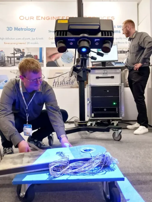
The project begins directly on the customer’s premises. The scanner plus workstation are made for mobile use, so the scanning engineer can set it up directly on the shop floor, for instance. With only limited space needed, it is possible to scan parts from small to very large scales at high accuracy (+/-0.025 mm for 1 m³ measurement volume). A stereo camera records the reflections of blue light that is projected onto the inspected structure. This works for a variety of surface characteristics and sizes by combining multiple scans. Also, not only plain surfaces can be scanned, but more complex geometries as well.
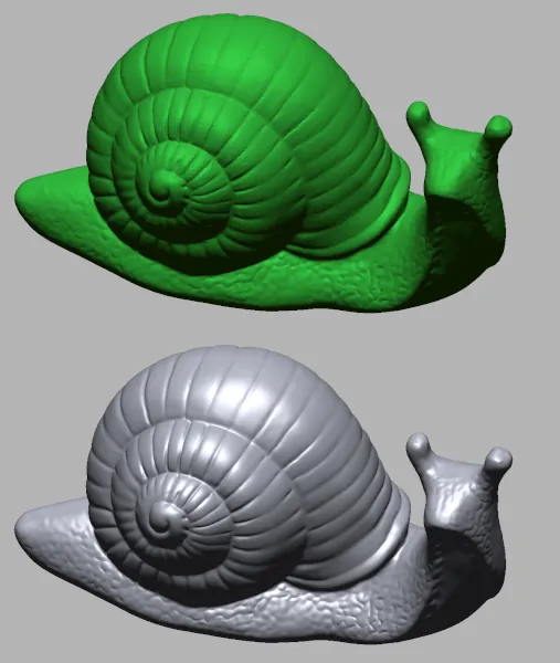
Thanks to the high resolution, the scanning engineer retrieves a polygon mesh that reveals even the slightest deformations and other surface defects. With this digital representation of the measuring data, the engineers carry on with the analysis. This step is possible either directly on-site – thanks to the quick scanning process – or at an external workstation.

One step beyond
So far, the 3D metrology scan has already delivered valuable information. Both scanning data and evaluation reports can be exported in several formats and provide crucial information on a part’s structural integrity. However, the Testia team can provide many more benefits with a few extra steps. Next point of order is the target-actual comparison, in other words comparing the measured data to what it actually should be on a flawless structure or part.
If the corresponding target data is already available, the comparison is a matter of a few clicks in the software. This rapid process is even suitable for in-line quality control of serial production. The software includes everything needed for quality control: Import target data, run the automated search for deviations in the measured data, and export the results.
If, however, there is no target data, it can be derived from the metrology data: Back at Testia, the reverse engineering expert utilizes the point cloud of the scan to create an optimized digital 3D model. All defects of the original part are reflected in the scan, too, like a digital twin. But now, this model is redrawn into optimal shape. To achieve this, the reverse engineer utilizes regular geometries: For example, when the original part includes a cubical shape with a few dents, this will be replaced by a clean cube in the 3D model. More complex shapes will be reconstructed by a combination of regular geometries and freeform shapes. The resulting CAD file does not only represent the ideal geometry without defects, it has an optimized file size as well. Because regular geometries can be stored much more effectively than the high-resolution polygon mesh, which is not needed anymore at this end point of the process.
Measure, analyze, improve
With the reverse-engineered CAD file at hand, the customer is able to let a replacement be manufactured for the defective part, jig or tool. It can go even further than an exact replication – if desired, Testia can even implement bespoke adjustments in the new 3D model. Shop floor workers might suggest a better placement of handles on a tool, for instance. Or an old jig’s supporting structure could be overdimensioned and a more suitable smaller replacement would better fit into the production line. What has been unthinkable beforehand will now be possible thanks to the reverse engineering team.
The beauty of the entire process is that it allows for both complexity and simplicity; detailed measurements as well as easily feasible improvements. The result is a flawless 3D model as the most reliable basis to manufacture replacements for worn-out components. Nightmares about production outages due to broken ancient tools can be a thing of the past.
Learn more about Testia’s 3D metrology services and reverse engineering capabilities or directly get in touch with our 3D metrology team.

